
Introduction
Over 90% of CubeSats rely on deployable structures—solar panels, antennas, magnetometer booms—to bridge a fundamental design constraint: they must be compact enough to fit inside a launch vehicle fairing yet fully functional once on-orbit. This reliance comes with significant risk. Historical data shows that 41.3% of small satellites experienced total or partial mission failure between 2000 and 2016, with deployable mechanism failures among the most common causes of mission loss.
The challenge intensifies for small satellite teams operating with limited budgets, compressed timelines, and less experienced engineering staff. As launch costs drop and access to orbit widens—2,790 smallsats launched in 2024 alone, representing 97% of all spacecraft—tolerance for failure shrinks accordingly.
Simply scaling down mechanisms from larger spacecraft doesn't work. Purpose-built design discipline is required.
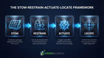
This post introduces a structured four-stage framework—Stow, Restrain, Actuate, Locate—that helps engineers systematically select the right approach at each stage of deployment. The framework assumes you've already solved the upstream problem: getting your satellite to orbit affordably. That's where purpose-built launch solutions like Green Launch's hydrogen light-gas propulsion system enter the picture, reducing the cost barrier that has historically limited how often small teams can fly and iterate.
Key Takeaways
- Small satellite deployment mechanisms enable compact launch stowage and full on-orbit functionality—over 90% of CubeSats depend on them
- The four-stage Stow-Restrain-Actuate-Locate framework organizes design choices and their inherent trade-offs
- Stow approach and restraint mechanism are interdependent—incompatible pairings cause frequent design failures
- Actuation ranges from passive strain energy (zero power, fast) to motor-driven systems (precise, complex)
- Proven practices like early prototyping and flight-representative testing dramatically improve mission success rates
Defining the Framework: The Four Stages of Satellite Deployment
The full deployment process encompasses eight stages: stow, restrain, initial unstow, guide geometry, guide speed, actuate, locate, and latch. Four of these—Stow, Restrain, Actuate, and Locate—most directly drive design outcomes and are the focus of this framework. The remaining stages matter, but they largely follow from choices made at these four decision points. Here's what each one demands from the designer.
Stow
Stowing compacts the deployable to fit within the launch vehicle envelope. The stow approach is the foundational design decision — it shapes compatibility with every subsequent stage and constrains what actuation methods are viable. Everything downstream follows from this choice.
Restrain
Restraints lock the deployable in its stowed position through the high-vibration, high-shock launch environment and release it on command. Three variables drive restraint design:
- Holding force: How much load must the restraint survive without slipping or fatiguing
- Release shock: How much impulse the deployable — and surrounding structure — can tolerate at release
- Resettability: Whether the mechanism must be reset for repeated ground testing
Actuate
Actuation transfers energy to move the deployable from stowed to deployed state. The options span a wide range:
- Passive — strain energy stored in the structure itself, or discrete spring mechanisms
- Active — motors, shape memory alloys, or inflation systems
Passive approaches are preferred for simplicity and reliability when precise deployment control isn't required.
Locate
Locating — and latching — establishes the final deployed geometry. Applications vary widely: body-mounted solar panels tolerate loose positioning, while high-frequency reflectarray antennas and deployable telescope mirrors demand tight precision. Location accuracy requirements should drive mechanism choice, not the reverse.
Stowing and Restraint: Preparing Deployables for Launch
Fold-Based and Compact Stow Approaches
The primary stow approaches offer distinct trade-offs between packaging efficiency, deployment complexity, and reliability:
Parallel folds (Z-fold and tri-fold):
- Most common for flat solar panel arrays
- Simple 1-degree-of-freedom deployment prevents panel intersection
- Lower packaging efficiency consumes larger surface areas
- Can block instruments or outward-facing solar cells pre-deployment
- Example: EnduroSat's 3U deployable solar array uses Z-fold hinges for reliable, repeatable deployment
Origami and kirigami folds:
- Achieve extreme packaging efficiency with up to 1:7 stowed-to-deployed surface ratios
- Enable single degree-of-freedom deployment despite complex geometries
- Require specialized expertise in fold pattern engineering
- Example: SolarCube demonstrates origami-inspired design in a 1U CubeSat, achieving 100W power generation from minimal volume
Telescopic stowage:
- Provides linear extension with high deployed rigidity at the root
- Moderate packaging efficiency limited by largest concentric tube segment
- Friction-sensitive; requires careful lubrication selection
- Example: NMTTM mission deployed a 5-meter non-magnetic telescopic mast for magnetometer isolation
Spooled and Coiled Approaches for Long Deployables
Spooled systems wrap deployables tightly around a central mandrel. This approach efficiently packages tethers, dipole antennas, and large membranes. The TEPCE mission successfully deployed a 1,030-meter conductive tether wrapped around a 51mm diameter core. However, spooled systems are vulnerable to "bird-caging" (uncontrolled expansion and jamming) if tension isn't maintained during deployment.
Coiled systems push the deployable against an outer perimeter constraint. This inherently manages bird-caging risk through radial containment, but requires more complex perimeter mechanisms with rollers or constant-force springs to maintain controlled tension.
Restraint Mechanisms: From Burn Wires to Release Nuts
| Mechanism Type | Holding Force | Shock Level | Key Characteristics |
|---|---|---|---|
| Burn wires | Dependent on tie-down cable (e.g., Vectran) | Near-zero shock | 2.4-7.2 second cut time; ultra-lightweight; can be built in-house; workmanship-dependent |
| SMA pin pullers | 5-1,000 lbf | Low shock (<100ms function) | High flight heritage; resettable; commercially available; potentially slow and friction-sensitive |
| Release nuts | 1,360-72,000 lbf | <300g to <1,500g depending on preload | Inherently bolted joint; familiar tooling; high reliability |

Burn wires offer the lowest mass and cost but require careful workmanship—power requirements change between ground and space environments. SMA pin pullers and release nuts provide higher holding forces with proven flight heritage, making them the preferred choice for larger deployables.
Pyrotechnic Restraints and the Small Satellite Trade-Off
Pyrotechnic cutters deliver high force, rapid release, and proven reliability, including the capability to cut metal cable. However, they impose a significant limitation for small satellites: shock loads often exceed 10,000g SRS, potentially damaging surrounding systems.
Launch providers increasingly restrict pyrotechnics on rideshare missions. SpaceX's Rideshare Payload User's Guide explicitly prohibits uncontained pyrotechnics like frangible nuts. This makes non-pyrotechnic alternatives the default for most small satellite programs seeking rideshare access.
Stow-Restrain Compatibility
Stow approach and restraint choice are not independent decisions. Not every stow approach works with every restraint type:
- Parallel fold solar panels typically use burn wires or pin pullers at hinge locations
- Spooled systems often require launch locks to prevent bird-caging during vibration
- Telescopic booms need axial restraints that release without imparting lateral loads
The Momentus Vigoride-3 solar array failure illustrates stow-restrain interface risk: a connector pin in a hold-down bracket failed to release, preventing deployment entirely. Ground testing must perfectly replicate flight hardware to catch these interface failures before launch.
Actuation and Location: Executing Reliable On-Orbit Deployment
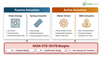
Passive vs. Active Actuation: Choosing the Right Energy Source
Passive actuation uses stored energy:
Strain energy deployment:
- The structure's own elastic energy drives deployment
- Zero power draw, high reliability
- Fast and sometimes uncontrolled
- Prone to reaching unintended stable states if not properly guided
- Common in deployable tape-spring booms
Spring actuation:
- Separate spring components provide deployment force
- High flight heritage, highly customizable
- Spring force varies with displacement—must account for this in margin analysis
- Fatigue management essential for ground testing cycles
Active actuation provides control:
Motor-driven systems:
- Enable precise deployment control and anomaly recovery
- Require electronics, higher power budget, and careful gearbox design for space thermal environment
- Can reverse direction if deployment stalls
Shape Memory Alloy (SMA) actuators:
- Slow, controlled actuation
- Temperature-dependent behavior requires thermal analysis
- Often used in pin pullers rather than primary actuation
NASA-STD-5017B mandates strict margins: 3× force/torque margin from analysis, 2× for qualification testing, and 1× for redundant "one-spring-out" scenarios. Failure to meet these margins during design review is grounds for mission disqualification — not a risk to be traded away.
Why Momentum-Only Actuation Should Be Avoided
Those margin requirements also explain why NASA-STD-5017B specifically prohibits relying solely on restraint-release momentum to drive deployment. If motion stops before the mechanism reaches its final state, it will not restart once the stopping force is removed.
This eliminates all anomaly-recovery options. Tether deployments are the most common failure case — friction or snagging halts motion with no recovery path, and the mission is effectively lost.
Location Approaches: Matching Accuracy to Mission Need
Loose hinges (deployment accuracy worse than 0.5°):
- Standard for CubeSat solar panels
- Low cost, reliable, simple
- Sufficient for power generation where precise orientation isn't critical
Precision hinges (accuracy better than 0.5°):
- High-tolerance pins and hard stops
- Used for reflectarray antennas and telescope mirrors
- Advanced High-Strain Composite hinges achieve sub-micron piston precision (0.53 µm) and angular precision within 5.9 µrad
- Adjustable hard stops enable post-assembly tuning
Kinematic mounts:
- Exactly constrained six-point contact
- Micron-level repeatability
- Used when instrument alignment is critical
- Deep Impact mission achieved in-flight alignment predictions within 60 µrad using optical alignment cubes near kinematic interfaces
Inflation as a Special Case of Actuation and Location
Inflatable deployables use compressed gas to expand a membrane into its operating shape — handling both actuation and location in a single mechanism. That packaging efficiency makes them attractive for small satellites, but the tradeoffs are significant.
Advantages:
- High packaging efficiency
- No rigid mechanism required
- Can achieve large deployed volumes from minimal stowed volume
Significant disadvantages:
- Hard to test at flight-representative pressure and temperature
- Geometry tends toward spherical/cylindrical shapes, limiting design flexibility
- Requires rigidization to maintain shape if pressure is lost
- Workmanship errors in soft goods lead to leaking
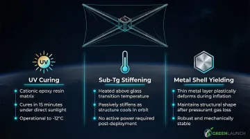
Rigidization methods:
- UV curing: Rigidization-on-Command (ROC) cationic epoxy resins cure in sunlight, completing cure after 15 minutes of UV exposure at temperatures as low as -12°C
- Sub-Tg stiffening: Materials heated above glass transition temperature during deployment, then passively rigidize as they cool in space
- Metal shell yielding: Thin metal layers plastically deform during inflation, maintaining shape after gas loss
The InflateSail 3U CubeSat successfully deployed a 1-meter inflatable mast and 10-square-meter drag sail, demonstrating viability for drag-sail applications.
Key Design Practices for Deployment Reliability
Reduce the number of deployments first. Before designing a deployable, verify it's truly necessary. If unavoidable, minimize the number of actuations required and reduce actuators in parallel and series. Each additional deployment event multiplies failure risk, power demand, and command complexity. Self-sequenced designs—where one deployable's motion mechanically triggers the next—can reduce actuator count while maintaining deployment order.
Prototype early and often. Deployment dynamics are highly non-linear, so analysis alone rarely gives you confident design answers. Start at low physical fidelity, iterate rapidly, and progressively increase prototype fidelity as the design matures. A failure caught on the bench during week two costs a fraction of what an on-orbit anomaly costs in mission loss and schedule recovery — particularly for small satellite teams operating on tight development timelines.
Test as you fly. Create a diagnostic baseline:
- Gravity offloading: Wheels under the structure or ceiling cables simulate microgravity deployment
- Cold ambient-pressure testing: Approximates thermal vacuum for lubrication validation
- Vibration and shock testing: Validates launch survivability
- Data collection: Record deployment in the same way the spacecraft will on orbit—accelerometers, strain gauges, timing data—to enable future anomaly diagnosis
Challenges and Future Directions for Small Satellite Deployables
Aperture stagnation creates a persistent challenge: while instruments continue to miniaturize, the physics governing antenna aperture, radar resolution, and optical collection area remain unchanged. Deployable mechanisms are growing to represent a significant fraction of small satellite mass and volume. As documented in recent research, this shifts the cost center of missions and creates new attitude control challenges during and after deployment.
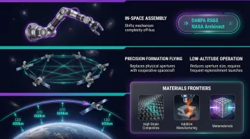
Three architectural approaches are gaining traction as alternatives or complements to traditional onboard deployables:
- In-space assembly shifts mechanism complexity away from the satellite bus — robotic construction on-orbit enables structure reuse across multiple deployment locations. DARPA's RSGS program and NASA's OSAM-1/Archinaut missions have demonstrated both robotic manipulation and additive manufacturing of extended structures directly in orbit.
- Precision formation flying replaces physical apertures with distributed spacecraft working cooperatively, using highly accurate attitude control and propulsion to enable synthetic aperture and interferometry at scale.
- Low-altitude operation reduces required aperture size through decreased ground distance. The tradeoff: satellites at 300 km altitude have lifetimes under a year without active drag compensation, which raises the importance of frequent, low-cost replenishment launches for sustained coverage.
Materials-level frontiers represent near-term technology bets:
- High-strain composites enable novel stow geometries previously impossible with traditional materials
- Additive manufacturing allows cost-efficient, topology-optimized mechanism parts with integrated flexures
- Metamaterials incorporate mechanisms at the material scale itself, blurring the line between structure and mechanism
Together, these directions suggest the next generation of small satellite deployables will be defined less by mechanical ingenuity alone and more by how well architecture, materials, and launch infrastructure are co-designed from the start.
Frequently Asked Questions
How much does it cost to launch a small satellite?
Launch costs range from $10,000–$50,000 for rideshare CubeSat slots to several million dollars for dedicated small launch vehicles. Rideshare programs and reusable rockets have pushed prices down considerably. For acceleration-tolerant payloads, Green Launch's hydrogen light-gas system targets $100/lb — among the lowest per-pound pricing available.
Can anyone launch a CubeSat?
Yes, but regulatory hurdles apply: FCC spectrum licensing, ITU frequency coordination for international operations, and range safety approval from your launch provider. Commercial rideshare programs have made access practical for universities, startups, and research organizations that can clear those requirements.
What are the 4 types of satellites?
Satellites are commonly classified by size: large (>1,200 kg), medium (601-1,200 kg), small/microsatellite (11-200 kg), and nanosatellite/CubeSat (1-10 kg). Alternatively, they're classified by function: communications, Earth observation, navigation, and scientific research. Small satellites are the fastest-growing segment, representing 97% of all spacecraft launched in 2024.
What is an example of a deployable structure?
Concrete examples include Planet Labs' Dove constellation using four spring-loaded deployable solar arrays in a "dart" configuration, the MarCO CubeSats' deployable flat-panel X-band reflectarray antenna that transmitted 8 kbps telemetry from Mars, and magnetometer booms like Ex-Alta 1's 60 cm folding aluminum boom that isolates sensitive sensors from spacecraft electromagnetic noise.
What is the smallest satellite launched?
The smallest launched to date are femtosatellites and ChipSats in the sub-100 gram range. KickSat-2 deployed Sprite ChipSats under 10 grams each — thumbnail-scale platforms that still incorporate burn wire-released wire antennas, showing deployment engineering applies even at the extreme low end.