
Introduction
In hypervelocity ballistic systems, bore diameter and caliber set the physical limits of what a light gas gun (LGG) can accomplish — from peak chamber pressure to terminal muzzle velocity. These specifications govern how propellant gas energy transfers to the projectile across every stage of the gun.
Engineers and researchers frequently underestimate how bore parameters interact with propellant gas dynamics, projectile mass, and multi-stage configurations. Undersized bores fracture projectiles under peak pressure; oversized bores allow gas blowby and produce velocity shortfalls.
This article covers what bore and caliber specifications mean in LGG design, typical ranges across single-stage, two-stage, and three-stage configurations, and the failure modes that follow from incorrect sizing. If you're designing a research gun for impact testing or an orbital launch system like those Green Launch has developed, getting these parameters right determines whether your system hits target velocity — or never fires twice.
Key Takeaways
- Bore diameter sets the cross-sectional area that controls pressure transmission to the projectile base
- Caliber in LGGs is driven by propellant gas choice, chambrage ratio, projectile mass, and target velocity — each factor constrains the others
- Two-stage systems typically use 20–100 mm launch tube bores; the pump tube is intentionally larger to generate the pressure ratio needed for high-velocity launch
- Incorrect bore sizing causes pressure loss, projectile damage, bore erosion, or catastrophic failure
- Engineering margins are structurally and thermodynamically necessary — they account for real failure modes, not worst-case guesswork
What Bore and Caliber Represent in a Light Gas Gun
Defining Bore as a Physical Boundary
Bore refers to the internal diameter of the launch tube (and separately, the pump tube) in a light gas gun system. Caliber in LGGs specifically denotes the bore diameter of the final launch barrel—the stage that imparts terminal velocity to the projectile. Unlike firearms conventions where caliber simply describes bullet diameter, in LGG systems caliber is a coupled design parameter with thermodynamic and structural consequences.
Bore diameter determines cross-sectional area (A), which appears in every governing equation: chamber volume, propellant mass ratios, projectile acceleration, and peak pressure on the projectile face. The area relationship A = π(D/2)² means that small changes in diameter produce nonlinear changes in area and performance.
For example, increasing bore diameter from 28 mm to 30 mm represents just a 7% dimensional change but yields approximately a 15% increase in cross-sectional area, altering predicted pressures and velocities measurably.
Multi-Stage Bore Configuration and Chambrage
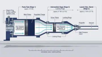
In a two-stage or three-stage LGG, each stage has its own bore diameter. The pump tube (first stage, larger bore) compresses the light gas, which then drives the projectile through the launch tube (second stage, smaller bore). The bore diameter ratio between stages—known as chambrage—is a critical design parameter formally defined as the ratio of pump tube cross-sectional area (A₁) to launch tube cross-sectional area (A₂).
Higher chambrage ratios allow more compressed gas energy to be delivered to the projectile, but require precise matching of chamber length and bore to avoid pressure loss at the transition. A chambrage area ratio of 4:1 produces approximately 10% higher exit velocity compared to no chambrage.
Gains plateau with further increases unless chamber length is also optimized — making chambrage one of the few design variables where more is not unconditionally better. Bore is fixed at manufacture and cannot be adjusted in the field, which means chambrage decisions made during design lock in the performance ceiling of the system.
How Real Operating Conditions Affect Bore Performance
Bore is fixed at manufacture, but its effective behavior shifts under real firing conditions:
- Barrel wall elasticity: Radial wall motion under high pressure causes elastic deformation, with pdV work done by expanding gas on bore walls representing a measurable energy loss
- Thermal expansion: Extreme gas temperatures cause bore materials to expand temporarily during firing, altering effective internal diameter
- Bore erosion: Repeated high-velocity firings gradually increase bore diameter through thermal erosion
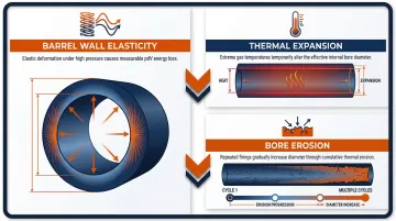
Propellant gas choice (hydrogen vs. helium) interacts directly with bore sizing. Helium produces higher sound speeds but also peak gas temperatures reaching 6,360 K compared to 1,880 K with hydrogen. Bore materials and diameters must be selected to tolerate these thermal loads. Helium causes severe erosion in second-stage barrels under repeated use, which is why hydrogen is typically preferred despite marginally lower performance.
Bore Diameter Ranges Across Light Gas Gun Configurations
Bore diameter in LGGs spans a wide range depending on stage count, mission payload, and target velocity. There is no single universal "standard" caliber; specifications are derived from the coupled system requirements of each design.
Nominal Bore Ranges by Stage and System Type
Single-Stage LGG Systems:
Single-stage configurations generally use smaller calibers with velocity ceilings around 2–3 km/s, suitable for ballistic testing and hypervelocity impact research:
- Sandia National Laboratories: 100 mm compressed gas gun (velocities to 1 km/s)
- Russian Federal Nuclear Center: 44 mm bore one-stage light-gas gun (impact velocity up to 1.6 km/s)
Two-Stage LGG Configurations:
Two-stage systems commonly feature pump tube diameters of 50–150 mm driving launch tubes of 20–40 mm bore:
- LLNL Intermediate Two-Stage Gun: 28 mm launch tube bore, 9 m barrel length, firing a 37 g projectile at approximately 6.2 km/s
- SwRI Large Two-Stage LGG: 115 mm diameter pump tube, 38 mm diameter launch tube, 22 meters long, top speed 7 km/s
- AEDC Range G: Interchangeable barrels of 84 mm, 102 mm, and 203 mm, with a 356 mm pumping system
Three-Stage Configurations:
The second-stage launch tube becomes the pump tube for a third, smaller-bore barrel:
- LLNL Three-Stage Gun: 12.1 mm third-stage bore diameter achieving projectile velocities in the 16–20 km/s range with a titanium projectile
- Sandia Three-Stage Gun: Demonstrated velocities up to 15.8 km/s with a 6 mm-diameter × 0.56 mm thick titanium projectile
Chambrage Ratios and Their Effect on Achievable Velocity
Chambrage area ratios of 4:1 (pump tube to launch tube) are well-documented and produce approximately 10% higher exit velocity compared to no chambrage. However, gains plateau with further increases in area ratio unless chamber length is also optimized — equal chamber volumes produce nearly the same velocity regardless of how that volume is distributed between area and length.
For space-access applications, these tradeoffs take on an additional dimension. Green Launch's light-gas gun architecture — designed for suborbital and orbital payload delivery — selects bore and chambrage specifications not just for peak velocity but for sustained structural integrity across repeated launch cycles. That constraint tightens allowable bore tolerances significantly compared to single-use research guns. Green Launch's testing at Yuma Proving Ground verifies bore condition across successive firing cycles, confirming that the system maintains consistent performance as shot count accumulates.
Safe Operating Margins in Bore Sizing
Bore diameter is typically specified with margins against peak chamber pressure limits. For example, peak projectile face pressures are kept at 2.5 GPa for titanium alloy, well below the ~5.5 GPa spall limit. Bore area influences how that pressure distributes across the projectile base.
Those same margins must also absorb manufacturing tolerances and bore wear that accumulates across multiple shots. Undersized tolerances lead to accelerated projectile sealing failure; oversized bore leads to gas bypass and velocity loss. A bore dimension deviation of even 1 mm in a 28 mm barrel represents a ~7% area change, altering predicted pressures and velocities measurably.
Key Technical Properties Governed by Bore and Caliber Specification
Bore diameter defines the physical constraints within which pressure, temperature, velocity, and mass interact — and each of these four properties responds differently to changes in caliber.
Property 1: Pressure Distribution and Peak Projectile Face Pressure
The force on the projectile base equals pressure multiplied by bore cross-sectional area (F = P × A). For a given propellant energy, a smaller bore concentrates pressure more intensely on the projectile. Sizing the bore too small for a given projectile mass produces pressure spikes that can fracture or vaporize the projectile; sizing it too large reduces acceleration efficiency.
In multi-stage systems, bore area reduction between stages is the mechanism by which gas energy is concentrated into the smaller, faster final projectile. LLNL's three-stage design deliberately limits peak projectile base pressure to 2.5 GPa—less than half the ~5.5 GPa spall strength of its titanium alloy projectile—to prevent in-bore spall fracture.
Property 2: Propellant Gas Mass and Fill Pressure Sensitivity
The mass of propellant gas in the pump tube scales with bore area and tube length. Bore diameter therefore controls the gas-to-projectile mass ratio — a primary driver of velocity efficiency that must be matched to the pressure profile established in Property 1.
In the three-stage LLNL example, a helium fill mass of ~4.13 g at 0.46 MPa was calculated from the third-stage bore area of 1.158 cm², showing directly how bore area sets fill conditions. These interdependencies carry forward into barrel geometry — specifically, how bore diameter and length combine to drive gasdynamic losses.
Property 3: Bore-to-Length Ratio and Gasdynamic Loss Mechanisms
The bore diameter combined with barrel length (L) defines the L/D ratio, which governs three key loss mechanisms:
- Gasdynamic drag: Turbulent boundary layer growth along the bore wall
- Convective heat loss: From hot propellant gas to the bore surface
- pdV work: Done by expanding gas on bore walls under elastic deformation
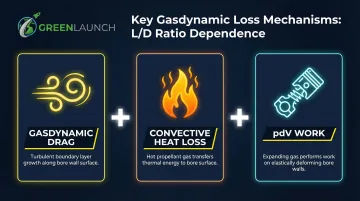
Narrower bores with long barrels increase drag and thermal losses disproportionately. Increasing launch tube length-to-diameter ratio (L_LT/D_LT) increases muzzle velocity up to a certain threshold, beyond which frictional losses hinder further velocity gains. That velocity ceiling, in turn, shapes the sabot design constraints that caliber imposes on the projectile.
Property 4: Projectile Geometry and Sabot Design Constraints
Bore caliber sets the maximum projectile diameter and drives the sabot design—the carrier structure that seals the bore and transfers pressure to sub-caliber projectiles. Mismatches between bore diameter, sabot outer diameter, and projectile diameter result in gas leakage past the seal (blowby), reducing effective pressure on the projectile base and distorting predicted velocity.
Sandia researchers documented that in-bore sabot erosion leads to gas blowby, causing 18 kbar precursor pressure spikes 25 nanoseconds before impact and generating opaque smoke that blinds VISAR laser diagnostics. A wedge-ring sabot design, which expands the fins to maintain higher contact pressure with the barrel wall than the driving pressure, successfully prevents blowby.
How Bore and Caliber Are Specified, Measured, and Validated
Bore specification is both a manufacturing requirement (dimensional tolerance on the barrel ID) and an operational check (verified before and after each firing campaign to detect wear and erosion).
Specification and Documentation
Bore diameter in research and defense LGG systems is typically defined in engineering drawings with tolerance bands (e.g., ±0.01–0.05 mm depending on caliber). These tolerances feed directly into analytical models—a bore dimension deviation of even 1 mm in a 28 mm barrel represents a ~7% area change, altering predicted pressures and velocities measurably.
Published standards or institutional practices from AEDC, Sandia, and LLNL documentation formally record bore specs for reference and performance modeling.
Measurement and Verification Methods
Bore diameter is measured using:
- Precision bore gauges: Mechanical measurements offer superior accuracy for assessing deformed or yielded bore conditions post-firing
- Air gauges: Used for initial bore profiling, though mechanical measurements provide greater accuracy when inspecting post-firing launch tubes
- Coordinate Measuring Machines (CMM): For straightness and roundness verification
Post-firing inspection checks for bore erosion (surface roughening, diameter growth near the breech) and barreling (non-uniform wear along the bore length). In high-use research guns, bore liners may be used and replaced periodically.
NASA optimization studies identify Tantalum as the preferred bore liner material over Rhenium or steel. Its superior ductility, lower Young's modulus, and high melting point effectively eliminate bore erosion in high-cycle or extreme-velocity (>10 km/s) systems, with demonstrated muzzle velocities reaching 12–13 km/s.
These material and dimensional findings translate directly into field validation practice. Green Launch's testing program at Yuma Proving Ground demonstrates this approach: engineers verify bore condition across repeated firing cycles to confirm system reliability for space-access missions.
Implications of Incorrect Bore Sizing on Performance and Safety
Bore diameter is upstream of every other performance variable, so an incorrectly specified bore propagates errors through pressure calculations, gas mass requirements, projectile design, and structural load predictions.
Performance Loss and Failure Mechanisms
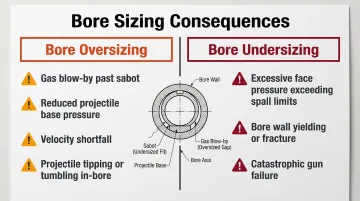
Consequences of Bore Oversizing:
- Gas blow-by past the sabot
- Reduced projectile base pressure
- Velocity shortfall
- Potential projectile tipping or tumbling in-bore from asymmetric pressure
Consequences of Bore Undersizing:
- Excessive projectile face pressure exceeding material spall limits
- Bore wall overpressure leading to yielding or fracture
- In extreme cases, catastrophic gun failure
Peak projectile pressure must be maintained well below the material spall strength—a hard structural limit with no safe margin for error. For titanium alloy, peak pressure is limited to 2.5 GPa against a ~5.5 GPa spall strength to prevent in-bore spall fracture.
Wear, Erosion, and Long-Term Bore Degradation
Even correctly sized bores degrade over time. Hot propellant gas (particularly helium plasma at high temperatures) causes thermal erosion of bore surfaces, gradually increasing the effective diameter and reducing sealing efficiency.
NASA Ames data shows that thermal bore erosion — typically ~0.0025 cm diameter increase per shot — injects molten steel droplets into the hydrogen propellant, raising gas molecular weight and cutting muzzle velocities by 2 to 4 km/s at the high end.
CFD performance models must account for propellant "loading" by ablated bore material to correctly predict these muzzle velocity deficits.
In single-use third-stage barrels (as in three-stage LGG designs), designers replace the barrel after each shot. In reusable systems, bore wear tracking is essential to maintaining specification.
Common Misinterpretations of Bore and Caliber in LGG Design
Don't treat caliber as equivalent to firearms conventions. In LGGs, bore diameter is a system-level parameter with direct thermodynamic and structural consequences, not simply a descriptor of projectile size. The pump tube and launch tube are different calibers by design, and conflating them leads to incorrect performance predictions.
Published LGG bore specifications don't transfer directly to new designs. Propellant gas type, projectile material, chamber geometry, and stage count all shift the optimal bore diameter for a given velocity target — applying nominal values from existing systems without adjustment produces unreliable results.
Frequently Asked Questions
What is a light gas gun?
A light gas gun is a ballistic launcher that uses a low-molecular-weight propellant gas (typically hydrogen or helium)—compressed by a piston or combustion driver—to accelerate projectiles to hypervelocities unattainable with conventional powder guns.
What is the maximum velocity of a light gas gun?
Two-stage LGGs are theoretically limited to approximately 10 km/s (set by the sound speed of hydrogen), while three-stage configurations have demonstrated velocities in the 15–20 km/s range. Bore diameter and stage geometry are key factors in approaching these limits.
What are the types of light gas guns?
Single-stage LGGs use a simple gas driver (~2 km/s). Two-stage LGGs compress light gas through a piston-driven pump tube to reach ~6–10 km/s. Three-stage designs add a smaller-bore final stage to push velocities into the 15–20 km/s range.
How does a two-stage light gas gun work?
In a two-stage LGG, a powder charge or combustion driver propels a heavy piston down a large-bore pump tube, compressing the light gas (typically hydrogen) until a burst diaphragm ruptures. The high-pressure gas then accelerates a sub-caliber projectile down the smaller-bore launch tube.
How does bore diameter affect projectile velocity in a light gas gun?
Bore diameter sets the cross-sectional area over which propellant gas pressure acts on the projectile base. A larger area ratio between pump tube and launch tube concentrates more energy into the projectile, enabling higher velocities up to the limit set by the propellant gas's sound speed.
What is chambrage in a light gas gun and why does it matter?
Chambrage is the ratio of pump tube cross-sectional area to launch tube cross-sectional area. Optimizing this ratio—alongside chamber length—maximizes launch velocity while keeping peak pressures within safe structural limits for both the projectile and barrel.