Introduction
In a fully pressurized light-gas launcher, the release trigger system is the last line of control before a payload accelerates to hypervelocity. This electromechanical subsystem governs the exact moment of propellant release — and any timing error propagates directly into velocity error at the muzzle.
For aerospace engineers, defense researchers, and organizations working with light-gas guns or ballistic launchers, milliseconds matter. Trigger timing variation translates directly to muzzle velocity scatter, affecting everything from orbital payload delivery to aerodynamic test data quality.
At operating pressures that can exceed 90,000 psi, failure modes include barrel rupture or unintended detonation. Precision timing and multi-layer safety design aren't optional — they define whether a program succeeds.
This article covers what big shot launcher release trigger systems are, how they function, their key components, available configurations, and why timing precision and safety interlocks define mission success in high-velocity launch applications.
Key Takeaways
- Release trigger systems hold multi-ton preloads and release stored energy only on a precise electrical fire command
- Sear mechanisms require aerospace-grade AISI 4340 steel with ion nitriding to survive extreme contact forces
- ±150 µs timing jitter degrades muzzle velocity consistency in hypervelocity testing
- MIL-STD-1316F multi-layer safety interlocks eliminate single-point failures and prevent unintended launches
What Is a Big Shot Launcher Release Trigger System?
A release trigger system is the electromechanical or pyrotechnic subsystem responsible for initiating the controlled release of high-pressure gas or projectile energy in big shot launchers. Unlike firearm triggers that manage relatively modest pressures and single-use cartridges, these systems must hold extreme static preloads — sometimes exceeding several tons — while maintaining microsecond-level timing precision across repeated firing cycles.
The trigger system acts as the final gate in the launch sequence. Once the launcher reaches operating pressure — up to 90,000 psi in some configurations — all stored pneumatic energy remains locked behind the trigger mechanism until a precisely timed release command is issued.
This differs from conventional ballistic systems, where millisecond tolerances are acceptable. In big shot applications, timing must resolve to the microsecond level. A single mistimed release can destroy expensive test hardware or compromise mission-critical data.
"Big Shot Launcher" refers to large-caliber, high-velocity platforms used in ballistic testing, hypervelocity research, and space access applications. These systems require purpose-engineered trigger assemblies — adapted commercial components simply cannot meet the demands.
The consequences of failure are severe:
- Premature release causes pressure loss and velocity shortfalls, leaving payloads short of target conditions
- Delayed release creates pressure spikes that can rupture barrel sections or damage acceleration-sensitive payloads
Key Components of a Release Trigger System
Sear and Latch Mechanism
The sear serves as the primary mechanical retaining element, holding the firing pin or piston in the cocked position under extreme static load. In launcher-class applications, sear components face loading conditions that would cause commercial-grade hardware to yield or fracture within a single firing cycle.
Material selection is governed by aerospace metallurgy standards. High-strength alloy steels such as AISI 4340 and precipitation-hardening stainless steels like 17-4 PH are standard, with AISI 4340 commonly nitrided to achieve surface hardness up to Rc 60. Ion nitriding to case depths of 0.004–0.008 inches ensures the sear contact surfaces resist galling and wear under the repeated high-contact-stress cycles typical of multi-shot test programs.
Actuator Assembly
The actuator converts control signals into mechanical release action. Three primary configurations dominate:
| Actuator Type | Response Time | Primary Advantage | Primary Limitation |
|---|---|---|---|
| Fast-response solenoid | < 0.1 ms | Precise electronic timing control | Requires complex drive circuits |
| Pneumatic valve | Slower (RC time-delay curve) | High force output; robust under harsh conditions | Air-flow friction limits speed |
| Pyrotechnic initiator | Instantaneous | High reliability (0.999 at 95% confidence) | Single-use; requires replacement |
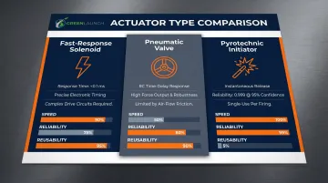
Fast-response solenoids enable sub-millisecond synchronization with diagnostic instrumentation—critical for test ranges where high-speed cameras and pressure transducers must trigger simultaneously. Pyrotechnic actuators offer guaranteed release in extreme temperature or shock environments, making them the choice for military flight termination systems and flight-test applications.
Control Interface and Fire Command Electronics
The trigger system interfaces with the launcher's fire control computer through signal conditioning circuits, command verification logic, and electronically enforced arming/disarming sequences. Modern systems incorporate differential drivers and physical circuit segregation to prevent electromagnetic interference from inducing uncommanded actuator energization.
MIL-STD-1316F mandates at least two independent safety features, each capable of preventing unintentional arming, with control and operation functionally isolated.
Fire command electronics must verify that all arming prerequisites are satisfied before energizing actuator circuits—a requirement enforced through hardware interlocks rather than software-only validation.
Safety Interlocks
Multiple independent safety mechanisms function in series:
- Pressure within acceptable operating range confirmed
- Barrel obstruction cleared and verified
- Safety keys inserted and acknowledged
- Operator fire command explicitly confirmed
MIL-STD-1901A requires that systems contain no single-point or common-mode failure prior to arming sequence initiation. This standard establishes the floor for interlock redundancy—but certain agency requirements go further. NASA MSFC-SPEC-3635 explicitly prohibits watchdog circuits that automatically shut down firing circuitry when parameters are violated. Safing must be accomplished through deliberate removal of the arm command by human operators, not autonomous abort systems.
Pressure Seal and Breech Interface
The trigger assembly must maintain high-integrity pressure seals at the breech face until the moment of sear release. Any leak path at this interface compromises both trigger timing precision and projectile velocity by bleeding off driver gas during the pressure buildup phase. Seal designs typically employ metal-to-metal contact surfaces with elastomeric O-rings as secondary barriers, all rated for the maximum operating pressure with adequate safety margins.
How the Release Trigger Mechanism Works Step by Step
Step 1: System Arming
The launcher transitions from safe to armed state through a deliberate sequence. The sear engages under preload, safety interlocks verify electronically through the fire control computer, and the trigger assembly pressure seal is confirmed at the breech interface. Continuity checks verify electrical connections to the actuator, and safing pins are removed to enable power delivery to firing circuits.
Step 2: Pressure Buildup and Hold
Driver gas—typically hydrogen or helium in light-gas guns—is pumped or generated to operating pressure while the sear holds the piston or valve closed. During this phase, sear components sustain multi-ton static loads without yielding. Material fatigue is a critical design factor: repeated high-stress cycles cause microcrack propagation in under-hardened components, ultimately leading to sear failure mid-pressurization.
Step 3: Fire Command Issuance
The operator issues a fire command through the control interface. Modern systems incorporate two-step arming-and-fire sequences: first, an ARM command that energizes intermediate relay circuits; second, a FIRE command that closes the final actuator circuit. Electronic confirmation verifies each step before proceeding, eliminating single-point command failures. In microsecond-precision applications, engineers measure and compensate the full signal chain—from operator input to actuator energization—for electrical delay.
Step 4: Sear Release and Energy Transfer
Upon actuator activation, the sear disengages rapidly—within microseconds for solenoid-actuated systems. The stored pneumatic energy releases into the barrel as a controlled pressure wave, accelerating the projectile. Sear disengagement speed and completeness govern muzzle velocity consistency: an incomplete release bleeds off pressure and reduces projectile acceleration.
Step 5: Post-Fire Reset and Inspection
After firing, engineers inspect and partially recondition trigger components between firing cycles. Each inspection covers:
- Sear contact surfaces — checked for galling or cracking
- Seal O-rings — replaced when compression set exceeds specification
- Actuator electrical resistance — verified to detect coil degradation
Types of Release Trigger Configurations
Mechanical Sear-Based Triggers
Purely mechanical configurations use a latch released by a cam or linkage. These systems offer simplicity and robustness—no electrical components means no electromagnetic interference vulnerability. However, they lack the timing precision needed for high-frequency test applications or synchronized data acquisition.
Electromagnetic (Solenoid) Triggers
Solenoid-actuated triggers enable precise electronic timing control, with response times under 0.1 milliseconds achievable in fast-response configurations. Test ranges use these systems where synchronized instrumentation requires sub-millisecond trigger accuracy. They are, however, vulnerable to electromagnetic interference—shielding and differential drive circuits are required to prevent false triggering.
Pyrotechnic Release Systems
Small pyrotechnic cartridges actuate the release mechanism in applications demanding absolute reliability under extreme conditions. Flight termination systems and space-rated hardware use pyrotechnic actuators because they function reliably across wide temperature ranges and high-shock environments. Single-use operation is the core constraint: each firing requires cartridge replacement and a full inspection before the next deployment.
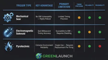
Quick comparison of trigger types:
| Configuration | Key Advantage | Primary Limitation |
|---|---|---|
| Mechanical sear | No EMI vulnerability; highly robust | Limited timing precision |
| Electromagnetic (solenoid) | Sub-millisecond timing accuracy | Susceptible to EMI; needs shielding |
| Pyrotechnic | Extreme-environment reliability | Single-use; requires replacement per firing |
Precision Timing and Safety Considerations
Timing Tolerance Requirements
Trigger release timing must be repeatable to tight tolerances. In ballistic test launchers, timing variation translates directly to muzzle velocity scatter, affecting projectile accuracy and experimental data quality. Sandia National Laboratories discovered that optical trigger systems can suffer from ±150 µs of jitter due to "ghost signals" from hydrogen plasma blow-by—timing uncertainty that directly degrades velocity consistency in hypervelocity testing.
To mitigate jitter, facilities employ laser-induced diaphragm rupture and high-resolution diagnostics that record pressure data every 5 microseconds, enabling precise characterization of timing performance across firing cycles.
Redundancy and Fail-Safe Design
Military and aerospace-grade trigger systems are built so that no single-component failure causes an unintended launch or a failure to fire. Standard safeguards include:
- Redundant actuators or dual-sear configurations that remain operational if one path fails
- Watchdog electronics that drive the system to a safe state on power loss or circuit fault
- Physical separation of redundant circuits to eliminate common-cause failures
Personnel Safety and Range Safety Integration
Release trigger systems integrate with broader range safety architectures. Physical barriers, remote-fire requirements, and real-time arming state communication to range safety officers are standard. Range safety officers issue fire commands from reinforced control rooms positioned hundreds of feet from the launcher, with surveillance cameras confirming personnel clearance before gas pressurization begins.
Applications in High-Velocity Launch Systems
Ballistic Research and Hypervelocity Testing
Big shot launcher release trigger systems support a range of high-stakes research applications:
- Aerodynamic testing at supersonic and hypersonic velocities
- Warhead development and terminal ballistics validation
- Materials impact research for spacecraft shielding qualification
Trigger precision directly affects repeatability: if timing jitter introduces ±2% velocity variation, impact test data becomes unreliable for validating computational models or qualifying spacecraft shielding materials.
NASA Ames increased projectile impact velocity capability to 8 km/s through light-gas gun optimization, with design specifications requiring at least 20 shots per gun barrel and 200 shots per high-pressure coupling—cycle-life targets that demand robust trigger component design.
These same precision and durability requirements extend beyond the laboratory into operational launch environments.
Space Access via Light-Gas Gun Launchers
Advanced release trigger systems underpin light-gas gun-based space launch concepts. Green Launch's proprietary light-gas propulsion technology uses hydrogen and oxygen gas propellant to achieve the high velocities needed for suborbital and orbital payload delivery. The company's precision gas injection scheme—designed to prevent errant detonation—depends on purpose-engineered trigger systems to ensure consistent muzzle velocities and safe operation across repeated launch cycles.
Green Launch has achieved velocities of 2.97 km/sec (Mach 9) in recent testing. That performance—the direct result of integrated trigger precision, gas injection control, and materials engineering—positions light-gas launchers as viable alternatives for deploying acceleration-tolerant CubeSat-class payloads to orbit.
Frequently Asked Questions
What is the primary function of a release trigger system in a big shot launcher?
The release trigger system holds the launcher in a loaded, pressurized state and initiates controlled release of stored pneumatic energy to propel the payload. Its precision directly determines velocity consistency and mission success by ensuring the gas charge releases at the exact commanded moment.
How does a big shot launcher trigger system differ from a conventional firearm trigger?
Big shot launcher triggers operate at vastly higher scales, sustaining preload forces measured in tons rather than pounds and managing pressures up to 90,000 psi. They incorporate multi-stage electronic safety interlocks, redundant actuator systems, and sub-millisecond timing control—none of which appear in standard firearm triggers.
What are the most common failure modes in launcher release trigger systems?
Sear wear or deformation under repeated high-load cycles, actuator signal failures due to electromagnetic interference, seal degradation at the breech interface allowing pressure bleed-off, and safety interlock bypass due to wiring faults or improper maintenance.
How is timing precision achieved in a release trigger system?
Solenoid or electromagnetic actuators controlled by precision fire command electronics achieve sub-millisecond timing, with signal latency measured and compensated in the fire control software. Advanced facilities use laser-triggered diaphragm rupture and microsecond-resolution diagnostics to characterize and minimize timing jitter across firing cycles.
What safety systems prevent accidental activation of a big shot launcher trigger?
Multi-layer interlock architecture includes mechanical sear locks, electronic arm/fire sequencing per MIL-STD-1316F, range safety system integration, and physical key-switch or two-person authorization requirements. All interlocks must be satisfied simultaneously, preventing any single-point failure from causing an unintended launch.
How often should release trigger components be inspected or replaced in high-cycle launcher applications?
Inspection frequency depends on operating pressure, cycle count, and manufacturer specifications. NASA Ames specifications require at least 200 shots per high-pressure coupling before replacement, with sear components inspected after each firing cycle; non-destructive inspection methods detect microcrack formation before catastrophic failure occurs.